
ACCA Manual D · Duct System Design
What Is Manual D? A Complete Guide to Residential Duct Design
Manual D is the ACCA standard for designing residential duct systems. It provides procedures for sizing and laying out ducts to deliver the required airflow to each room, based on the home's heating and cooling loads and the selected equipment.
The Manual D Standard Explained
Designing the Duct System to Match the Loads
Manual D is the ACCA (Air Conditioning Contractors of America) standard for residential duct system design. It provides procedures for sizing supply and return ducts, calculating design friction rates, and planning duct routes to deliver the required airflow.
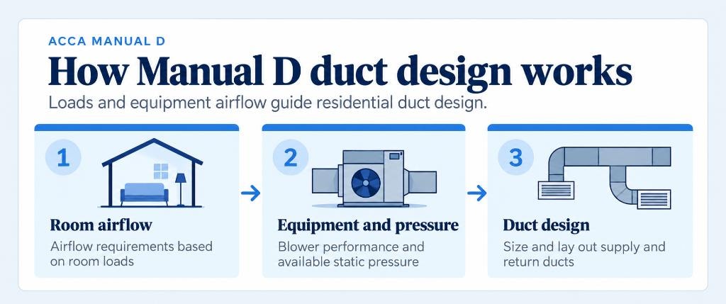
The design starts with the room-by-room heating and cooling loads from Manual J and the equipment and design airflow selected through Manual S. Room airflow requirements are expressed in cubic feet per minute (CFM). Manual D uses these requirements, manufacturer blower performance, and available static pressure to size the duct system.
Manual D is referenced in the International Residential Code (IRC) for duct design. Where required by the local permitting authority, duct design documentation is submitted with the Manual J and Manual S reports. Check local requirements for the applicable code edition and any additional forms or drawings.
Why Manual D Matters
Why Duct Design Is Not Guesswork
Airflow Distribution
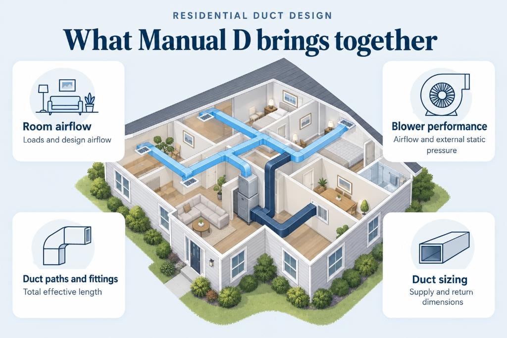
Room airflow requirements are based on the room-by-room heating and cooling loads and the selected system's design airflow. Manual D uses these requirements to design the supply and return duct system.
Friction Rate Calculation
Calculate the design friction rate using available static pressure and total effective length, including the resistance of fittings. This establishes the pressure-loss allowance used to size the ducts.
Duct Sizing
Size supply and return ducts for the required airflow using the design friction rate, duct material, and applicable velocity limits. Duct dimensions must account for both airflow resistance and air velocity.
Equipment Compatibility
Use manufacturer blower performance data to check that the selected equipment can deliver the design airflow at the anticipated external static pressure. Account for component pressure losses when determining the pressure available for the ducts.
Comfort and Balance
A duct system designed for room airflow requirements supports comfort throughout the home. Proper installation and airflow balancing are also needed; duct design alone does not guarantee uniform room temperatures.
Code Compliance
Where required by the local permitting authority, provide Manual D duct design documentation with the Manual J and Manual S reports. Confirm the applicable code edition and any required forms or drawings.
The Manual D Design Process
How Manual D Duct Design Works
Determine Room Airflow Requirements
Use the room-by-room Manual J loads and the equipment's design airflow selected through Manual S to determine the required airflow for each room. Establish the airflow carried by each supply branch and trunk, and plan adequate return-air paths.
Calculate Available Static Pressure
Use manufacturer blower performance data at the design airflow to establish the external static pressure available. Subtract applicable component pressure losses to determine the pressure available for the ducts, accounting for which components are already included in the blower data.
Establish the Design Friction Rate
Determine the total effective length of the critical supply-and-return duct path, including straight ducts and fitting equivalent lengths. Calculate the design friction rate as available static pressure multiplied by 100, divided by total effective length in feet.
Size Supply and Return Ducts
Size each supply and return duct for its required airflow using the design friction rate and the appropriate duct-material data. Check applicable velocity limits and coordinate duct routes, fittings, and dimensions with the home's construction.
Document the Design
Record duct sizes, design airflow values, routes, fittings, blower data, and the static-pressure and friction-rate calculations. Provide the duct layout and supporting documentation required for the project and local permit review.
Manual J · Manual S · Manual D
Manual D in the Complete Design Process
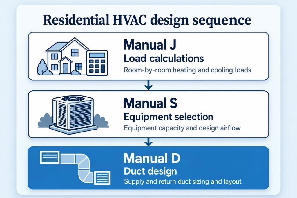
Manual J, Manual S, and Manual D work together in residential HVAC design. Manual J calculates the home's room-by-room heating and cooling loads. Manual S uses those loads and manufacturer performance data to select equipment and establish design airflow. Manual D uses the room airflow requirements, blower performance, and available static pressure to size and lay out the supply and return ducts. Changes to the loads, equipment, or airflow may require corresponding updates to the duct design.
Manual D Topics
Manual D Duct Design Topics
Manual D Duct Design: What It Is and Why It Matters
An introduction to the ACCA Manual D standard, its role in residential duct design, and why a calculated duct design is required for code-compliant HVAC installations.
Read moreManual J vs. Manual D: What's the Difference?
Manual J calculates heating and cooling loads. Manual D uses those loads to design the duct system. Learn how the two standards differ and why both are required.
Read moreHow Manual D Determines the Right Duct Size
Manual D sizes each duct using the design friction rate, required airflow, duct material data, and velocity limits. Learn how the sizing procedure works.
Read moreManual D Airflow and Static Pressure Explained
Airflow and static pressure are the two key variables in Manual D duct design. Learn how available static pressure and design friction rate are calculated and used.
Read moreWhat Information Is Needed for a Manual D Duct Design?
A Manual D duct design requires room airflow requirements from Manual J, equipment blower data from Manual S, duct routes, fitting types, and construction details.
Read moreManual D Duct Design for New Construction Homes
In new construction, Manual D duct design is coordinated with framing, insulation, and mechanical rough-in. Learn how the process works and what documentation is required.
Read moreManual D Duct Design for Existing Homes and HVAC Replacement
When replacing HVAC equipment in an existing home, Manual D procedures are used to evaluate whether the existing duct system can deliver the required airflow for the new equipment.
Read moreManual D Duct Sizing for Supply and Return Air
Manual D sizes both supply and return ducts using the design friction rate and required airflow. Learn how supply and return duct sizing works and why return air matters.
Read moreManual D Ductwork Layout: Balancing Airflow Throughout the Home
Duct routes, fitting types, and layout decisions affect total effective length and the pressure available for duct sizing. Learn how Manual D approaches ductwork layout.
Read moreManual D Duct Design Mistakes: Common Errors to Avoid
Common Manual D duct design errors include undersized ducts, excessive fitting losses, and duct systems not matched to the equipment's design airflow.
Read moreManual D and HVAC Comfort
A duct system designed to Manual D delivers the required airflow to each room, which supports consistent temperatures and comfort throughout the home.
Read moreGet a Price Quote & Order Our Manual J, S & D Services
Need help with a residential HVAC project? Load-Calculations.com provides Manual J load calculations, Manual S equipment selection, and Manual D duct design using ACCA methods. Visit the services page for pricing, project requirements, and submission instructions.